Week 3 Challenge: Circuits 3 and 4
This week I explored two different circuits. I had a pretty bad fever and flu aches the last three days, so my understanding and progress was somewhat hindered by not feeling well.
RGB LED
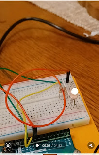
The first circuit had me use a 3 color LED. The light had 3 anodes as well as one extra long cathode going into ground. By playing with the code, I was able to create more colors than just the three "red, green, blue."
In the first build the only mistake I made (other than my usual typos when typing out the code) was to ignore the direction I connected the RGB. I flipped it around (wrong) so that the longer pin (Ground 2) was connected to the green wire which led back to port 11 instead of the white wire which led to the negative strip leading back to ground. This error led the light to blink only red. Simply turning it around and making sure the longer cathode pin connected to the ground, reversed my problem and made the light blink from blue to green (but not red). I double checked the connection to the #9 port to see why there was no red light. Securing the connection of the resistor ended up solving the problem and made all of the RGB lights to blink in a full spectrum with orange, magenta, pink, etc).
The Code
One interesting aspect was the analogWrite and showSpectrum() function which mimicked an analog connection allowing me to seamlessly transition and fade through the colors be allowing a range of 255 colors. I was fascinated that I was able to do this with just the code and that I didn't need the potentiometer. Here's where the combinations come in. By doing every combination of red, blue, and green, and every possible combination of "LOW, HIGH" paired with the lights, the led is able to blink more than just the red, green, blue colors, as well as combine to make new colors (for example having red and blue both "HIGH" at the same time creates purple, whereas having all the colors HIGH at the same time causes white). By using values in the 255 colors causes and allows natural looking fading between the colors and creates a seamless spectrum with a smooth transition.
Multiple LEDS
For circuit 4 I set up multiple LEDS. These were connected to 8 different ports and each had their own resistor. They had an index of 0-less than 7. The code (index = 0; index <= 7; index++)made since to me except for the index++. I'm assuming it is less than than the rgb led because less of a range is needed since they are blinking on and off and not transitioning between different colors. These lights had a delay of 100 milliseconds instead of 10.
Challenge
I tried using pieces of each code for the RGB led and multiple leds together. I was pretty ill this weekend and was unable to troubleshoot the two different PinModes needed for my code. I got stuck and will play with it through the rest of the week.
Final Reflections and Possible Extensions
I enjoyed playing with the different indexes and reversing the codes from 255 - 0 and 0 - 256. I have yet to understand what the ++ after the index is for but I will keep researching it. It is interesting to begin to gain an understanding of the codes and circuits needed for the fading RGB LEDs as well as multiple blinking LEDS while viewing all the Christmas lights displays at this time of year.


Comments
Post a Comment