Arduino Potentiometer Week 2 Blog Post
The Project
week I challenged my Arduino circuit understanding by working with a potentiometer. A potentiometer is an analog pin which can allow for a range between ON and OFF (HIGH and LOW) in the code, because the normal digital pins do not. A potentiometer is necessary for doing ranges such as the speed of blinking, brightness of the led (dimming), etc.
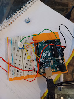
I connected my led circuit much like last week with my resister, ground, and 5v wires connected the same. My led light was again connected to 13 and my code was similar. The new variable was the poteniometer which was connected in a new circuit to the red and black wires (5v and ground) with a green wire taking an analog reading of the voltage back to the breadboard to be delayed by the code.
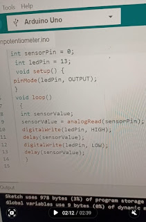
My understanding is that I had to create two circuits, one with the analog pin (my green wire) connecting from the middle leg of my potentiometer to the analog part of the breadboard and then read by the led via the computer code. Without the code stating that the sensor pin and sensor value would be in the delay, it wouldn't have allowed the potentiometer switch to have an effect. The analog signal is the measurement between the 0v and 5v. From A0 (the analog converter on the breadboard). The green wire sends the resistance from the ground to the potentiometer. The middle pin being the signal of the voltage between 0 and 5. I thought it was interesting that I didn’t have to configure the sensor pin as an input in the code because the analog pin was already reading the voltage from 0-5 as an input. The center pin is the input voltage going into the computer code to be read by the computer as how much voltage to be output into the led.
The Code
My Diagram of the Circuit
The main variable in this circuit is the middle pin of the potentiometer. It has built in it a sensor that is sensing the voltage on the circuit which is controlled by the amount of resistance in potentiometer. I don’t understand what number the analog write is putting out because it doesn’t seem to be the number of millivolts, but my understanding is that the middle pin is basically a resistor.
Troubleshooting/Changes to My Thinking
The first issue I had was that my potentiometer looked different than all the others online. The middle analog pin is a full 4 spaces back from the other two pins on the side (not parallel like in most other models). Because of this I had to make sure my circuit was fully connected using both side of the breadboard. I could not fit it similarly to the SIK tutorial because I did not have enough horizontal space next to the connecting wires. I made my wires and the pins on the potentiometer were aligned on the same metal strips and this modification did not cause any problems in getting my circuit to work.
my potentiometer
Another difference is I corrected my false understanding from last week that the resister had to "resist" electrons to protect the led light by going from the positive strip to the anode of the led. Instead I connected it from the cathode to the ground. It resisted just as well because in a circuit, it does not matter where the resistance is as long as it is part of the circuit.
To help me better understand the concept (and understand how a dimmer switch works), I connected the potentiometer via the green wire (middle of the potentiometer) to the led which created an actual dimmer switch by making a complete circuit with the potentiometer and caused variation in led BRIGHTNESS instead of having two circuits (one with the led and one with the potentiometer and depending on the code to create a delay (through the analog on the breadboard) and causing variables in the blinking SPEED.
Extensions
See what happens if you use two digital pins rather than on digital and one analog pin.
I could not change the blinking speed of the light with two digital pins even when I changed the code (sensor pin to the 10 port and the sensor value to digital read instead of analog read in the code itself). Digital read in the code only returns HIGH or LOW and analogRead returns any number from 0-1023, therefore digital read can not function as a time delay.
What happens if you replace analogWrite with digitalWrite and vice versa?
If you replace analogWrite with digitalWrite it will not read a voltage in between HIGH to LOW because digital read is incapable of this. If you replace digitalWrite with analogWrite it could work because the analog wire does receive and input of electricity from the port.
Can you control 2 lights with the same brightness or same blink rate?
Yes! I added a new led (a green one), connected to port 8, and added it to the code as ledPin8. I then programmed it in the code as digitalWrite ledPin8 and programmed it to be HIGH at the same time as the first ledPin (the one that was connected to 13) before the analog delay.
Can you control 2 lights with one potentiometer but have them controlled so that as one light gets dim, the other gets bright or one blinks fast while the other blinks slow?
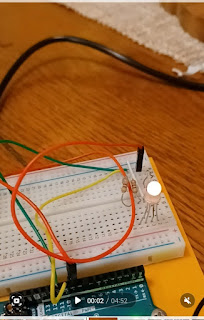
Kind of, the video below explains how I was able to make the lights blink at different times vs. the same time by making them blink HIGH and LOW respectively before the delay and then LOW to HIGH respectively after the delay. I would need more time to play with the circuit before I did one dim and one bright, or one fast and one slow as I couldn't figure out how to send different messages at the same time to each light.


Comments
Post a Comment