Arduino Week 1 Blog Post
This week I took a dive into beginner programming using the Arduino open-source electronics platform.
My challenge was to build a circuit on a breadboard and program a code to make an LED light blink. Simple enough for a beginning project I thought, so although I had some bumps along the way, I extended it to include a second LED light that remained constant while the first blinked.
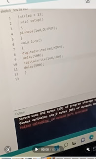
Below is a screenshot of my code. The blinking led light was labeled "13". "Void setup" begins a program whereas "void loop" has the program run until the power is disconnected. "Output" is the flow of electricity (the source being your computer) into the led light. I don't know quite why "led" must go before output and not the other way around. I also don't know if it is important to capitalize words such as "OUTPUT, HIGH or LOW" as playing around with capitalization didn't seem to make a difference. "HIGH" stands for "on" and "LOW" represents "off" which allowed for the program to cause the light to blink "on" and "off." "Delay 500" represents the delay between the "HIGH/LOW" or "on/off" functions. I switched between making the delay 500, 1000, and 2000. The greater the number the longer the delay, and therefore a higher delay, such as 2000, causes a slower blinking of the light. A shorter or lower number (500) on the delay causes the light to blink faster (which is what I ended up liking best and ending my code on.
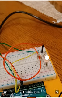
Below is a photo of my circuit on the breadboard. This was ironically more difficult to get right. I needed connecting wires as well as a resistor (to "resist" the amount of power going through and keep my led from burning out), and an led light. I thought I was successful with my first circuit (picture one) until I became concerned with the brightness of my light and realized my resistor was not a part of the circuit so my light was receiving unresisted power. I fixed this with the second circuit (picture two) using another wire to connect the cathode (short wire of the led back to the ground).
I was surprised at what a challenge building the circuit itself was, compared to the actual coding (proving you need practical application knowledge as well as theoretical). I did not initially include the extra wire connecting back to ground, causing my circuit to not be complete and my light not to blink. Once I remedied this problem, I got my light to blink my joy was shortlived, as I realized my light was way too bright and my resistor, while plugged in, was not part of the circuit. After remedying that problem, I got the blinking light to happily work, encouraging me to add the extension. My insecurity now that there is still an error, stems from the fact that I needed two separate wires connected to source in "port 1" and "port 13" respectively and did not make a complete circuit with both bulbs stemming from just one port (but I will keep working on it). The code in the computer I found relatively easy to understand although I am unclear what exactly the "void" function is for other than to represent that there is nothing before and after the program and that everything else but the program itself is "void?" One misconception I may have is my assumption that the "//" symbol turns a line of code into a comment so adding it to a code basically deletes that line of code when you run the program but I could be wrong.


Comments
Post a Comment