And For My Grand Finale................I Fried My Arduino Board!
This week we were supposed to create a project of our own using motors controlled by sensors.
Since my kit did not include a motion sensor (which is odd because I bought it from the Arduino site, I
decided to use a temperature sensor, and program it control the motor when the temperature increased (my plan
was to light a candle and move it close to the temperature sensor triggering the motor). While the concept
was cool, I ran into the problem of the motor itself not working, which I attributed to a problem in my code.
After an hour of troubleshooting and not getting anywhere, I decided to first get the motor itself to work
and then add the sensor later (probably my first mistake). I was able with the very simple code below
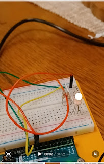
to get the motor to work but it started getting very hot (foreshadowing, I know). The below video
was sort of my initial tinkering before the disaster happened. I decided to take my circuit apart and calculate
how many volts the motor was using in comparison to the LED and other components I had worked with.
I then abandoned trying to use the temperature sensor altogether, and decided to research
and use a transistor, because their purpose is to help your Arduino handle components with
higher electrical requirements.
I was able to get the motor to run when I mistakenly used the thermistor instead of the transistor in a
circuit with the 5V pin and motor over the two end leads of the thermistor. I had the digital pin wired to
the center lead of the thermistor with a 570 ohm resistor. I think that this worked because the center pin
of the thermistor has no input characteristics (it is essentially a one way diode connected for output only)
and the two other leads of the thermistor have very little resistance. So, the motor was essentially getting
maximum current from the Arudino board (roughly 200 mA) which was enough to engage this particular
DC motor.
statements on that output to control the operation of the motor. Basically the output from the motorPIN
is a small current that switches the transistor open so that switches the transistor open so that a bigger current can
control the motor. I tried to calculate the resistance needed for the motor by calculating its voltage in comparison
to the other components I've worked with and by looking up their needed voltages online, but my math may
have been off.
However, I was not able to turn the DC motor when using a proper transistor in conjunction
with the 5V pin as a power source and the digitalpins as base current sources. I received two
transistor models with my Arduino kit - a BC547 transistor and MOSFET type transistor. Both of these
are NPN-type transistors that require a positive current on the base pin (center pin) to open the
connection between the collector pin (positive current) and emitter pin (ground current). The MOSFET
transistor is a relatively large unit which requires a high base pin current in order to open the
collector-emitter gate. The digitalpins of the Arduino kit are only rated for 20 mA with a maximum of 40
mA, so this would be insufficient for the larger MOSFET transistor. So instead I decided to use the
BC547 transistor. I connected the motor in a circuit with the BC547 transistor per diagrams I found
online, which includes a parallel diode circuit to protect the circuit from current backflows generated by
the motor spinning. When I connected the Arudino digital pin to the base pin of the BC547 under a 270
ohm resistor, which supplies approximately 18.5 mA of current, I was only able to achieve a flow of 30
mA from the collector to the emitter, which was insufficient to power the DC motor. The datasheet on the
BC547 indicates a current gain of 110 ma to 800 mA, which is considerably more than I was measuring.
My impression was that this was likely because I had a bad transistor, so I ordered 200 PN2222 NPN
transistors from Amazon (only $7). Unfortunately, I was achieving roughly the same CE current output
with the same setup on testing multiple PN2222 transistors.
Given my lack of results, I then made the risky decision to lower the resistance to the base pin of the
transistor even more (in retrospect, this wasn't such a great idea. I tried 2- 270 ohm resistors in parallel
to get a calculated resistance of 135 ohms. This still did not allow the motor to be powered (the plot thickens)
So I tried to send current to the base pin without any resistance. This was unfortunately a colossal mistake
as I observed a spark in the digital pins and they subsequently quit working. Every digital pin no longer
supplied any current. I had “fried” the digital output part of the board and could no longer use code to
control the circuitry. In panicking over this mistake, I started taking apart my circuit (without taking a picture)
and tried to build a simple circuit to see if I had indeed fried my Arduino board.
In doing more research, I found that I should be using an external power source to power the motor
rather than the 5V pin of the Arduino board since that will barely supply enough current (100mA) to power
a DC motor. I should probably have used a 9V battery to supply this current which would have been ample
to drive the motor. I’ve ordered a new Arduino board on amazon as well as different DC motors and plan
to keep experimenting.
ReplyForward |
.jpg)


Comments
Post a Comment