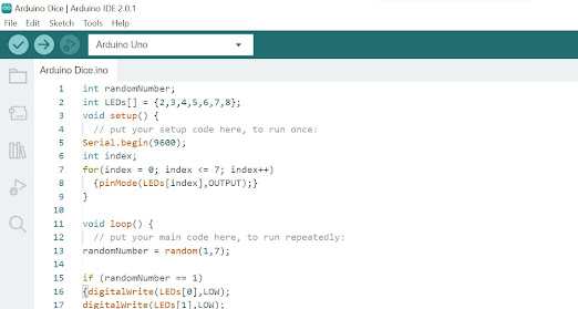
Arduino Dice Challenge The Project This week my challenge was to create a random number generator, with each LED representing the dots of a dice. This task was rather daunting as I didn't quite understand how random generators worked going in to this project. The Code In the initial setup, I labeled the individual LEDS connected them to a port. I found on the Arduino Help Boards that index++ means increase by increments of one (which I didn't understand last week) and added that to the random number generator. I then set my random number code to represent as dice patterns so for example, if the random number = 5, I set a pattern of LEDs making the dice "5" patte...
Posts
Showing posts from November, 2022
- Get link
- X
- Other Apps
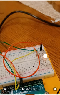
Week 3 Challenge: Circuits 3 and 4 This week I explored two different circuits. I had a pretty bad fever and flu aches the last three days, so my understanding and progress was somewhat hindered by not feeling well. RGB LED The first circuit had me use a 3 color LED. The light had 3 anodes as well as one extra long cathode going into ground. By playing with the code, I was able to create more colors than just the three "red, green, blue." In the first build the only mistake I made (other than my usual typos when typing out the code) was to ignore the direction I connected the RGB. I flipped it around (wrong) so that the longer pin (Ground 2) was connected to the green wire which led back to port 11 instead of the ...
- Get link
- X
- Other Apps
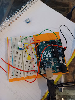
Arduino Potentiometer Week 2 Blog Post The Project week I challenged my Arduino circuit understanding by working with a potentiometer. A potentiometer is an analog pin which can allow for a range between ON and OFF (HIGH and LOW) in the code, because the normal digital pins do not. A potentiometer is necessary for doing ranges such as the speed of blinking, brightness of the led (dimming), etc. I connected my led circuit much like last week with my resister, ground, and 5v wires connected the same. My led light was again connected to 13 and my code was similar. The new variable was the poteniometer which was connected in a new circuit to the red a...
Arduino Week 1 Blog Post
- Get link
- X
- Other Apps
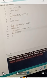
This week I took a dive into beginner programming using the Arduino open-source electronics platform. My challenge was to build a circuit on a breadboard and program a code to make an LED light blink. Simple enough for a beginning project I thought, so although I had some bumps along the way, I extended it to include a second LED light that remained constant while the first blinked. Below is a screenshot of my code. The blinking led light was labeled "13". "Void setup" begins a program whereas "void loop" has the program run until the power is disconnected. "Output" is the flow of electricity (the source being your computer) into the led light. I don't know quite why "led" must go before output and not the other way around. I also don't know if it is important to capitalize words such as "OUTPUT, HIGH or LOW" as playing around with capitalization didn't seem to make a difference. "HIGH" stands for ...