Posts

Makerspaces and Arduino Retrospective

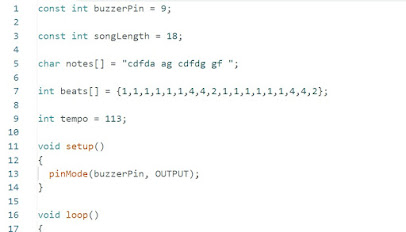
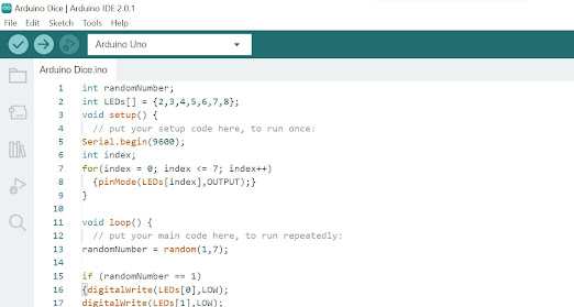
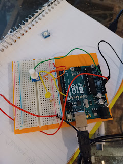
What was the build that you are most proud of and why? The Arduino build that was the most challenging and rewarding for me was the Dice random generator.  It was very challenging to figure out how to cause randomization in my code, but it was the most rewarding and I thought the most cool.  The following week where I did the very simple buzzer that played Christmas carols, was also very rewarding because it was the first time that I completely understood 100% of what I was doing and how to extend and challenge myself. ·            Go back to your first week and read each week's submission with an eye for personal growth. Where were you when you started and where did you end up? I  was worried about the coding in the beginning but that actually made the most sense to me, even though I still have to occasionally look up how to do new functions.  What surprisingly was the most challenging for me was the circuits themselves.  I was amazed and frustrated at how something as simple as n
Image
            And For My Grand Finale................I Fried My Arduino Board! This week we were supposed to create a project of our own using motors controlled by sensors. Since my kit did not include a motion sensor (which is odd because I bought it from the Arduino site, I decided to use a temperature sensor, and program it control the motor when the temperature increased (my plan was to light a candle and move it close to the temperature sensor triggering the motor). While the concept was cool, I ran into the problem of the motor itself not working, which I attributed to a problem in my code. After an hour of troubleshooting and not getting anywhere, I decided to first get the motor itself to work and then add the sensor later (probably my first mistake). I was able with the very simple code below to get the motor to work but it started getting very hot (foreshadowing, I know). The below video was sort of my initial tinkering before the disaster happened. I decided to take my ci

Week 5 Piezzo Buzzer Arduino Project

Image
                                    The Project         This week I thought I'd take a break from using the Arduino LED light challenges and work with a           Piezzo Buzzer on the bread board.  The Piezzo Buzzer makes a small beep when voltage is sent to           it. By sending different voltages you can change the tone of the beep and even compose little songs           for the buzzer to play! The Code   Photo of the Circuit Diagram Video My Learning I wanted to see what the Arduino program and breadboard could achieve outside of blinking LED light projects.  It was fun to see the program achieve sounds.  The circuit was very simple which allowed me to experiment and play around with the code to get different tones, instead of troubleshooting the circuit which is typically where I get bogged down.   I was a little daunted by the fact that my mini speaker Piezzo Buzzer looked slightly different than the buzzer on SIK Arduino kit (although I did get an official Arduino kit from
Image
                                                                            Arduino Dice Challenge The Project This week my challenge was to create a random number generator, with each LED representing the dots of a dice.  This task was rather daunting as I didn't quite understand how random generators worked going in to this project. The Code  In the initial setup, I labeled the individual LEDS connected them to a port.  I found on the Arduino Help Boards that index++ means increase by increments of one (which I didn't understand last week) and added that to the random number generator.  I then set my random number code to represent as dice patterns so for example, if the random number = 5,  I set a pattern of LEDs making the dice "5" pattern (with the four dots at four corners and one dot in the middle) to be HIGH with the rest of the LEDS set to LOW.  I used the "else if" function and the delay to 2000 because when I initially set it to 1000, the dice bli
Image
                                                                Week 3 Challenge: Circuits 3 and 4 This week I explored two different circuits.  I had a pretty bad fever and flu aches the last three days, so my understanding and progress was somewhat hindered by not feeling well. RGB LED The first circuit had me use a 3 color LED.  The light had 3 anodes as well as one extra long cathode going into ground.  By playing with the code, I was able to create more colors than just the three "red, green, blue." In the first build the only mistake I made (other than my usual typos when typing out the code) was to ignore the direction I connected the RGB.  I flipped it around (wrong) so that the longer pin (Ground 2) was connected to the green wire which led back to port 11 instead of the white wire which led to the negative strip leading back to ground.  This error led the light to blink only red.  Simply turning it around and making sure the longer cathode pin connected to the groun
Image
                                                                      Arduino Potentiometer Week 2 Blog Post The Project week I challenged my Arduino circuit understanding by working with a potentiometer.  A potentiometer is an analog pin which can allow for a range between ON and OFF (HIGH and LOW) in the code, because the normal digital pins do not.  A potentiometer is necessary for doing ranges such as the speed of blinking, brightness of the led (dimming), etc.   I connected my led circuit much like last week with my resister, ground, and 5v wires connected the same.  My led light was again connected to 13 and my code was similar.  The new variable was the poteniometer which was connected in a new circuit to the red and black wires (5v and ground) with a green wire taking an analog reading of the voltage back to the breadboard to be delayed by the code. My understanding is that I had to create two circuits, one with the analog pin (my green wire) connecting from the middle leg of m

Arduino Week 1 Blog Post

Image
 This week I took a dive into beginner programming using the Arduino open-source electronics platform. My challenge was to build a circuit on a breadboard and program a code to make an LED light blink.  Simple enough for a beginning project I thought, so although I had some bumps along the way, I extended it to include a second LED light that remained constant while the first blinked. Below is a screenshot of my code. The blinking led light was labeled "13".  "Void setup" begins a program whereas "void loop" has the program run until the power is disconnected.  "Output" is the flow of electricity (the source being your computer) into the led light.  I don't know quite why "led" must go before output and not the other way around.  I also don't know if it is important to capitalize words such as "OUTPUT, HIGH or LOW" as playing around with capitalization didn't seem to make a difference. "HIGH" stands for &